
Gina Build Guide

Table of Contents
- Tools and Equipment Checklist
- Flashing Guide
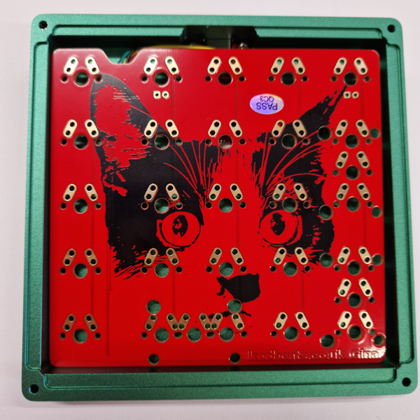
2.1 Checking the PCB
2.2 How to flash Gina PCB
2.3 Choosing your Layout - How to assemble Gina
3.1 Installing the PCB & Plate
3.2 Standard Orientation
3.3 Southpaw
3.4 Assembling Gina - Troubleshooting
4.1 Loading a VIA Design using JSON - Get in Touch
Tools & Check List
Tools: M2 Stainless Steel Hex (Allen Key), Tweezers
Check List:
- 1x Gina Case
- 1x Gina Plate
- 1x Gina Matrix/PCB
- 2x M2 25mm Screws
- 2x M2 12mm Screws
- 4x M2 4mm Screws
- 1x JST Cable
- 1x MCU/Daughter Board (Brain of the PCB)
- 4x Case Feet
- 1x Allen Key

2. Flashing Guide
2.1 How to check the Gina PCB/MCU
First, you will need to ensure the PCB/Matrix of the board doesn't have any issues and works as expected. At this point you do not have to flash the PCB, but you must have access to a computer/laptop. Connect the two components (MCU & PCB Matrix) with the supplied JST cable before plugging in a USB C. Ensure that the orientation of the JST cable connectors are the correct and flush. After you have connected the Gina MCU/PCB with a USB C cable, there should be a notification that a new device has connected to your system.
To test the PCB you can use either VIA using a pair of tweezers. For VIA, you can access software via this link: https://usevia.app/test. Using a tweezer - lightly press between the switch pad holes of the PCB Matrix. If your PCB is working as intended, it should register an input on on the VIA app.
For a more extensive guide on how to test your PCB using VIA please refer to this guide:
Note: Your Gina PCB/Matrix/Daughterboard should come pre-flashed and compatible with QMK/VIA. In chance that this is not the case then please continue reading this section.
2.2 How to flash your Gina PCB/MCU
Here is a comprehensive written guide on how to flash a PCB/MCU for all QMK based firmware:
In case you prefer to watch a video on how to install and use QMK to flash install the firmware to your Gina:
2.3 Choosing your layout

Once you have plugged in and checked that your Gina is properly flashed. You can change the orientation of Gina using VIA.
This step can be performed before or after you have soldered/assembled the board but we recommend you choose the layout you'd like to use and test the PCB with your chosen layout beforehand.

Left-Macro Column, Right Numpad (Standard) Important Note: The orientation denotes the side of the macro column.

Right-Macro Column, Left Numpad (Southpaw) Important Note: The orientation denotes the side of the macro column.
3. How to assemble your case
Please refer to the complete component set at the top of this post before attempting the build. Also note that Gina is designed to be highly versatile, so feel free to change and play around with any configuration that you desire, what is mentioned below is just a guideline on how to assemble Gina for the most common use cases.
3.1 Installing the daughterboard (MCU).
After ensuring the daughterboard and PCB are working as intended (refer to section 2), you will want to disconnect the daughter board from the PCB and lay inside the case where the USB-C cutout is. You will want to ensure that the USB-C port is flush (aligned) with the hole. Install the 4x M2 4mm screws in the correct holes of the daughterboard and in line with the holes of the case.

Installing the Daughter Board (MCU) to the Gina Bottom Case

Connecting the Daughter Board & PCB via JST Cable.
Installing the PCB & Plate
For a soldered build you will first need to install the stabilisers before installing the plate. After the plate has been placed you can place and solder the switches on. This guide will not cover how to solder a PCB/switches as there are a multitude of guides available on the internet and YouTube.
For a hot swap build, you can install the stabilisers and switches for the Gina, using them as an anchor for the plate.
Very cute cat. Left-Macro Column. Right Numpad (Standard Orientation).

Not as cute. Right-Macro Column, Left Numpad (Southpaw Orientation).
3.2 Standard (Right Hand Numpad Configuration)
For this configuration you will need:
- 22 MX Switches
- 3x2u sets of stabilisers
- 1 Gina Plate
You will first want to ensure that the switches and stabilisers are installed in the correct orientation. That will include, 3x2u 1.6mm stabilisers set on the bottom row (where the 0 key of the numpad sits) and two on the right hand column (where the + and Enter keys sit). The macro column should be oriented on the left side of the pad.

Left-Macro Column. Right Numpad (Standard Orientation). Assembled without the Top Case for clarity.
3.3 Southpaw (Left Hand Numpad Orientation)
For this configuration you will need:
- 22 MX Switches
- 3x2u sets of stabilisers
- 1 Gina Plate
You will first want to ensure that the switches and stabilisers are installed in the correct orientation. That will include, 3x2u 1.6mm stabilisers set on the bottom row (where the 0 key of the numpad sits) and two on the left hand column (where the + and Enter keys sit). The macro column should be oriented on the right side of the pad.

Left-Hand Orientation (Southpaw). Assembled without the Top Case for Clarity.
3.3 Ortholinear
For this configuration you will need:
- 25 Switches
- 1 Gina Plate
You will first want to ensure that the switches are all correctly positioned on the PCB and in the plate. Make sure that you have your desired column orientation before soldering / assembling the PCB.

Ortholinear layout of Gina in Southpaw. The plate & PCB can be flipped to allow for a standard ortholinear layout.
3.4 Assembling your Gina
After you have assembled and fitted your PCB with stabilisers and switches, align the plate in the correctly with the corner holes of the bottom case. Then carefully place the top case in the correct orientation as the PCB configuration.
You will then flip the board on its face, and lay it on a table or very carefully hold the pad in securely in one hand. Whilst the board is flipped upside down, use the M2 25mm screws to screw in the top half of the case until it's secure, making sure the plate is flush with the case.
Next, grab the M2 12mm screws and proceed to screw the bottom half of the case, keeping the plate and case flush the entire time. And that's it - you have successfully assembled Gina!
4. Troubleshooting
4.1 Loading a VIA Design using JSON
In the case that your Gina PCB is not showing up correctly onto VIA, you may need to load the design for Gina using the JSON File.
First, make sure that your PCB has been flashed and registered onto your system. Then click this link: https://usevia.app/design, which will take you to the VIA design tab. At the bottom of the VIA design page, next to "Load Draft Definition", upload the Gina JSON file to the software. You can find the JSON file for Gina under this section.
5. Get in Touch
If you are having issues with your Gina feel free to get in touch at the KeebCats discord server: https://discord.gg/HP8bt3EhDM
Alternatively, you can get in touch by emailing our support: hello@keebcats.co.uk